Midget,
Sorry I'm still a bit behind the blog curve here. This post is slightly out of sequence. Some photos of the block assembly from my last foray above the Cheddar Curtain:
A couple of photos of the modified main saddles, notice that the bearing oil feed holes no longer have a mismatch.......


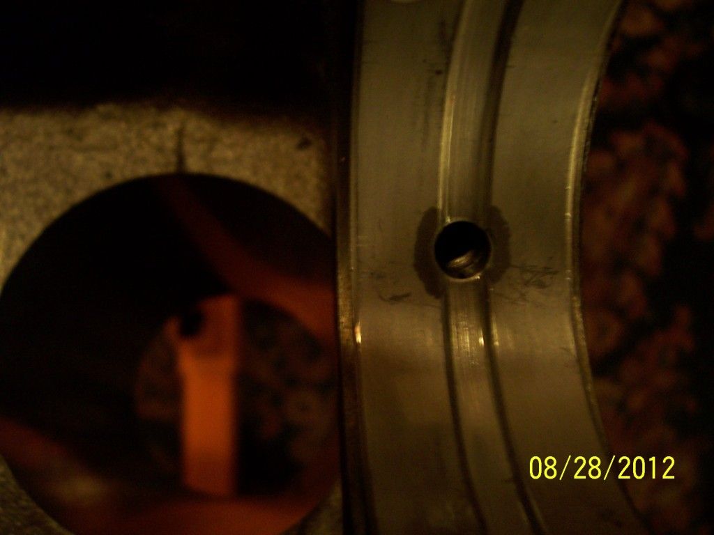
Closeup view of the #3 main saddle with the bearing installed and no mismatch between bearing oil feed hole & block oil feed passage. This is normal on #3 (because of the larger diameter oil feed passage in the block) and why the block was modified to obtain the same result for #1 & #2 ........

And finally, the completed block/crank/bearings/thrust washer assembly, ready for battle.......

For anybody who is following along: The bearing housing bore sizes were checked using a calibrated dial bore gauge & a calibrated micrometer. They were at the specification. The bearing clearances were calculated by measuring the crank with a micrometer and then using an inside micrometer to measure the assembled & torqued main bearings/caps/block. By adjusting the inside mike to the ID of the clamped bearings & then measuring the inside mike with the same mike used to check the crank, any errors or calibration problems between 2 micrometers can be avoided. Measuring the clearances can be done using a machinist's "snap gauge" and an outside micrometer, but I feel that method is more difficult, less accurate AND more subjective. Not saying it can't be done, just not my choice.
So the net result of the evening was: POSITIVE PROGRESS!!!! As opposed to negative progress...........

Son of Frankenstein/Palladin