Midget, et all,
Slightly behind the blog curve here, and I have several thoughts which I'm going to post separately, to keep my head from exploding.
On Midget's most recent foray beneath the 'Cheddar Curtain' we performed some block modifications (um, violations) on the stock BMC oiling system passages. The stock system requires some modifications to perform reliably at extended/higher revs/minute. Not necessarily in any order:
1 There should be some type of screen filter on the oil pickup pipe that extends into the sump. It prevents the stray shard from being sucked into the pump. Later model engines have a suitable screen filter/pickup pipe assembly that can be retrofitted to early engines using a bit of ingenuity.
2 You should be using the highest volume oil pump that will fit your cam drive/block combination. Some pump types are inherently better than others in that they utilize a taller (thicker) lobe/rotor combo. It should go without saying that the pump body casting & passages should be "ported"/smoothed. The corner supports for the rotor, near the inlet & outlet passages,
SHOULD NOT BE PORTED AWAY COMPLETELY!! MISMATCHES BETWEEN BLOCK PASSAGES & OIL PUMP PASSAGES SHOULD BE CORRECTED WITH "PORTING".
3 The small diameter oil transfer pipe, (which exits the block above the starter) and connects to the oil filter housing, is in my opinion too small for racing engines. In engines I have built up over the years, I have enlarged this pipe to an Aeroquip -8 or -10 line. This also requires enlarging the block and oil filter housing fitting threads to a compatible/suitable size. If you have to run a wet sump, and are allowed to run an "accumulator" (such as an "Accusump") plumb it in to this line.
4 I also enlarge the oil transfer passage from the filter housing to the main oil feed gallery.
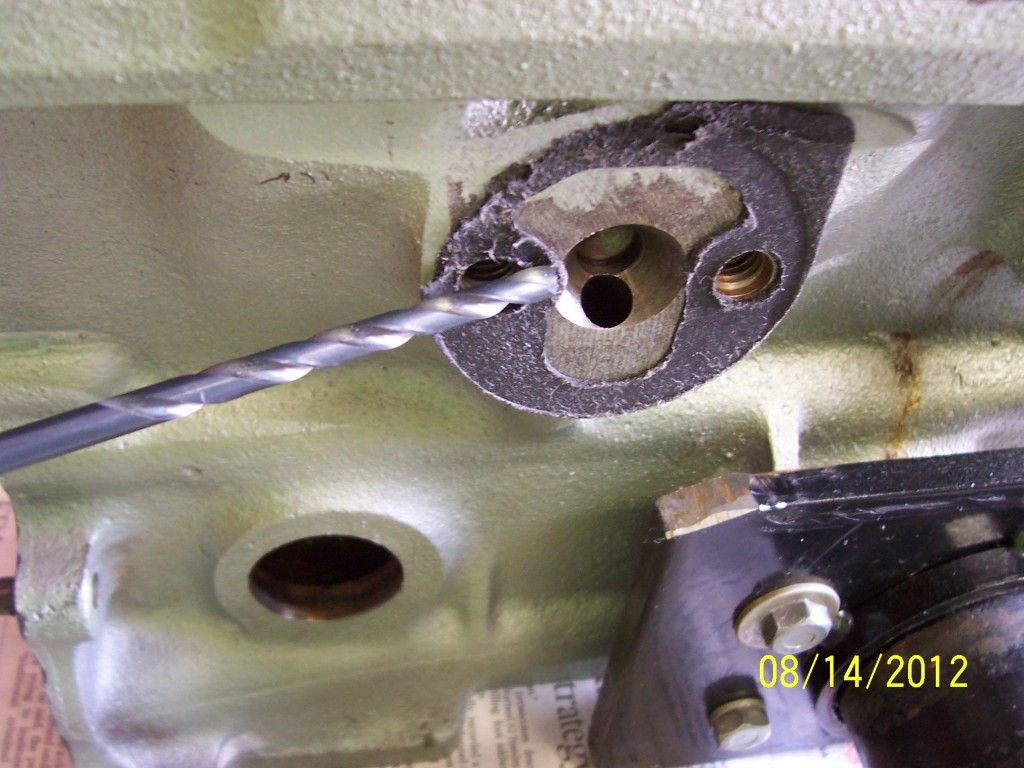
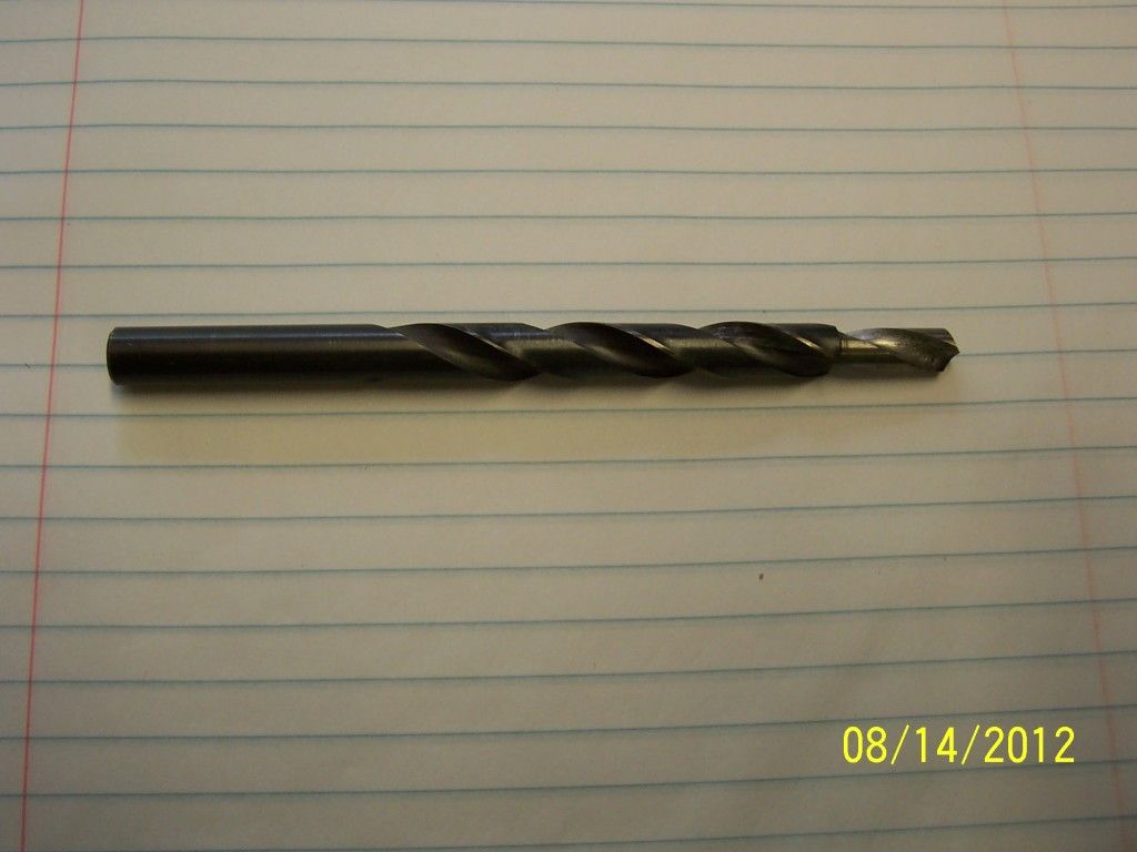
This passage starts out at 5/16" diameter. This can be carefully enlarged to 3/8" diameter using a piloted jobbers length (longer than standard length) drill bit similar to the one pictured below.
A word of caution is required here. The casting is "typically" thick enough in this area for this modification to be no problem.
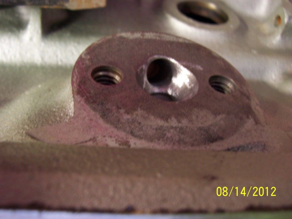
BUT, you must visually check beforehand!!!! The drilling must be done with some kind piloted bit/cutter to follow the original drilling. And you must stop drilling with the piloted drill when the pilot becomes visible in the main oil gallery. The drilling can then be finished carefully with a long length, standard point drill bit. As long as you stay centered on the original passage, you will intersect the main oil gallery. It may not be perfectly centered on the main oil gallery, but you are looking to increase the cross-sectional area of that transfer passage coming from the oil filter housing. I also "port" & smooth the entry to this passage on the block face as shown below.
5 The main oil gallery plugs (as well as the other oil system plugs) should be drilled/tapped for screw in plugs as suggested previously. (See reply #1331,
BMC Block Cleaning.)
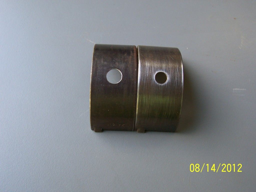
6 I have had lots of problems with the oil feed holes in the #1 & #2main bearing saddles being mis-aligned with the oil feed hole in Vandervell VP2 racing bearings. The problem exists because the oil feed passages for #'s 1&2 are 1/4" diameter, as opposed to #3 which is 5/16" diameter.
To solve this issue I utilize two methods. Method 1 is to carefully enlarge the oil feed hole in the bearing with a tapered reamer. This method can solve "slight" mis-alignment problems, as the feed hole cannot be enlarged too much. See photo below.
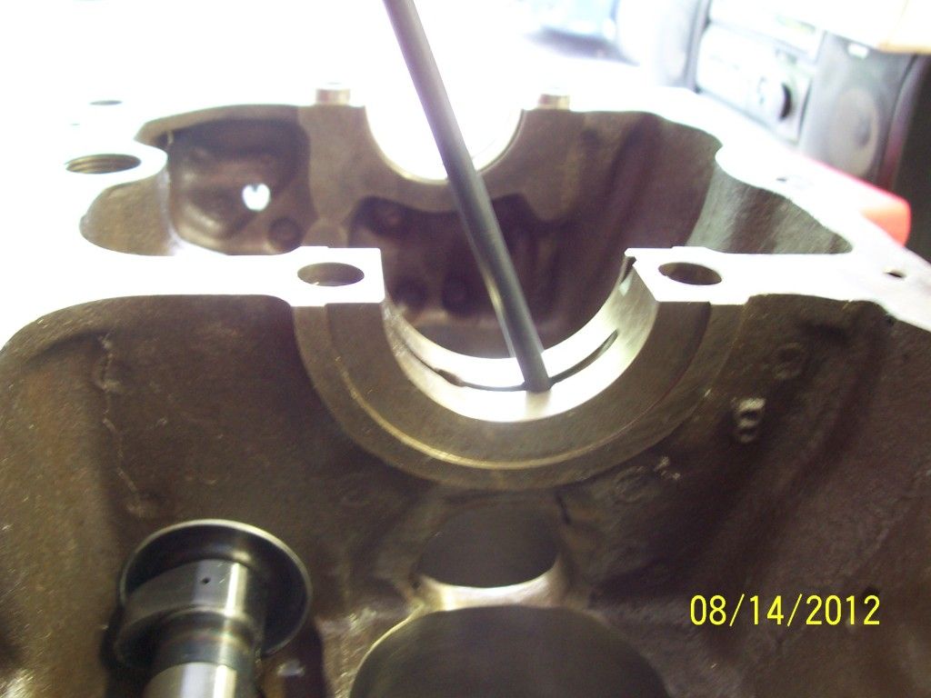
Most of the time though I have to use Method 2, which is to enlarge the oil feed passage in the block, about 1/4" deep, using a 5/16" drill with a 1/4" pilot ground on the nose as shown below.
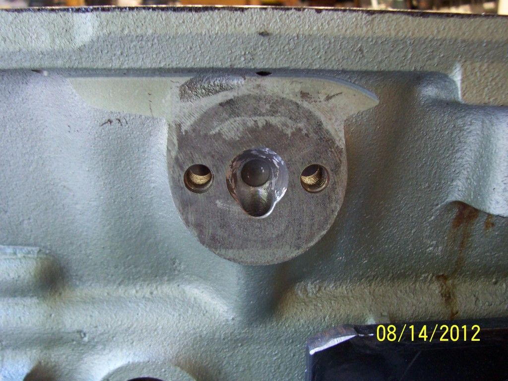
Here is a photo of the proper modification.

And a photo of both #1 & #2 main saddles as modified.
Either method, or both methods combined, can be used to correct this common misalignment problem.
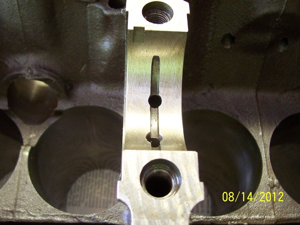
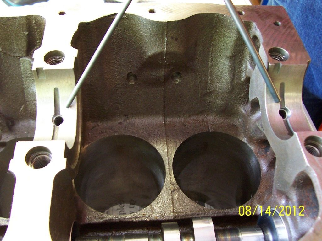
7 I have also had problems with bearing wear on the the #2 & #3 rod bearings. I believe this is related to the fact that #1 main feeds #1 rod; #3 main feeds #4 rod; and #2 main feeds #2 & #3 rods. As I noted before, the #2 main bearing oil feed passage, from the main oil gallery is only 1/4" diameter. That is the same as the #1 main, which feeds only 1 rod. The #3 main, still feeding only 1 rod, is 5/16" diameter. I have had good sucess by enlarging the #2 main bearing oil feed passage from 1/4" diameter to 5/16" diameter, (for a significant, 55%, cross sectional area increase), BUT there is a caveat as shown below:
Notice that this passage passes very close to the "window", under #2 main, that exists in some blocks. Additionally, some blocks, especially overbored ones, have boring reliefs (for honing) well below the bottom of the cylinder bores. Study the photo, and then your block carefully,
before drilling this passage. A MISTAKE IN MEASUREMENT OR JUDGEMENT HERE TURNS YOUR BLOCK INTO JUNK!!! There is a black marker line visible in the photo, just to the right of the "window". I measure the thickness of the casting here very carefully. I want to see a minimum of .56"/.63" here (measured longitudinally [fore & aft] in the bore relief area)
before drilling this passage from 1/4" diameter to 5/16" diameter. Chris has elected to leave his block at 1/4" diameter for this passage because his block is only .52" thick here.
Also of note: Some camshafts blanks have extra & overly large tappet and distributor drive gear oiling holes. A restrictor may be required to prevent noteable oil pressure/volume loss in the system. Another item to double check on. I'll dig up and post some photos on this.
Schematic diagrams of the oil system can be found in Vizard's books: Blue bible, page 352; Yellow pages, page 428.
That's it for now on the oil system.

Son of Frankenstein
PS: If you race a BMC, you need to think out of the box on the oiling system and the component parts.


 Topic: Milwaukee Midget (Read 3583721 times)