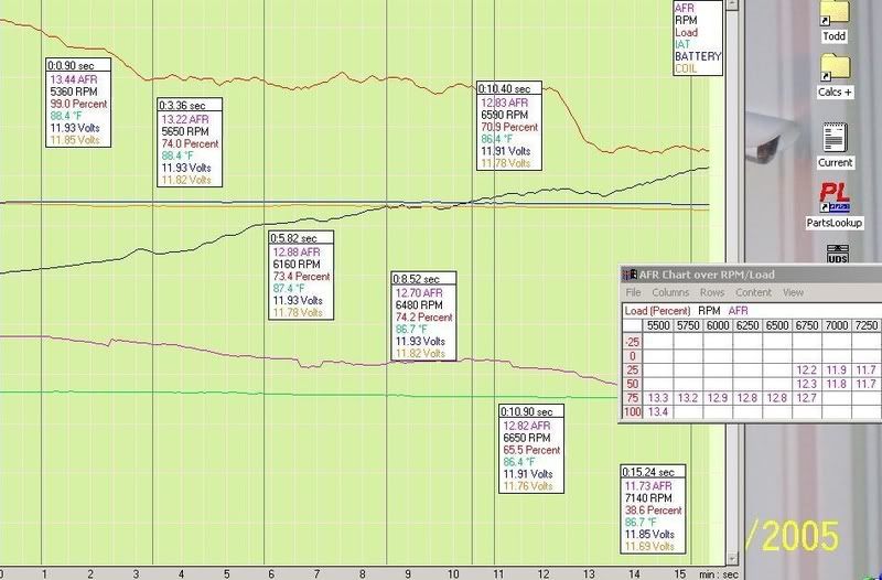
Todd that looks really good to me and as long as the logs look good that is all we care about.
Not the clearest looking on here, but very clear in logworks and valuable in many ways as you can see from just the few simple traces I have here a while back. Hasn't necessarily made me any faster(probably could of gone faster without it by now actually), but it's done me well on multiple levels of longevity which means I will eventually reach my goal... and even after a half decade of testing on the same motor I can still stick it right back in my street bike and keep on riding(well, unless I decide to ream her out "just one more time" this year and it decides enough is enough that is - lol).
Looks to me that you are plenty far from the end of the pipe.
Oh yea, no problem there. Deb run's on her bike (well past the collector) and I have used mine on literally hundreds of bikes now both on and off the dyno (even checked on of my pitbikes and my generator once).
The thing about WB sensors like these are their reaction to not only fresh air, but also to air pressure. The fresh air reaction is as one would think with a crack in a pipe or reversion(fresh air scavenge from the pipe end) causing lean readings.. fair enough and simple to check. You can use welding gloves to cover the end of the pipe to see if you're getting reversion(especially once you realize how the pressure effects the readings and can cause an increase or a decrease in afr readings), and you can use the gloves or even rags over the pipe in possible crack or leaking areas to see the decrease in afr if they exist(are sucking air).
Positive pressure on the sensor itself will give false readings as well (and although they are still relative to being lean or rich most of the time, they still won't be accurate). What will happen is that the increase of pressure on the sensor will make a lean condition appear much leaner, and a rich condition appear much richer then it actually is. This is with exception to something like a big amount of reversion being blocked by covering the end of the pipe like above(since that will not be increasing the lean reading from the fresh air, but actually decreasing the afr by blocking that fresh air), as opposed to an anti-reversion trap like in your picture(the scavenge pipe) should it cause a pressure increase on the end of the sensor... as this A-R trap is something that will show the afr enhancements faults as I described if not fully free flowing.
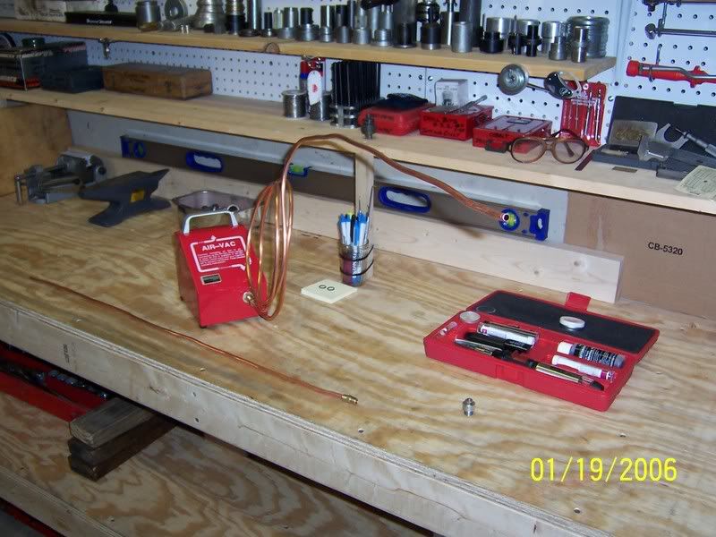
I have an external setup like that on a stand(made by innovate), and to make sure I don't get any pressure buildup I've connected a cheap air-vac(like to clear an a/c manifold) to help keep a negative pressure on the sensor all the time.
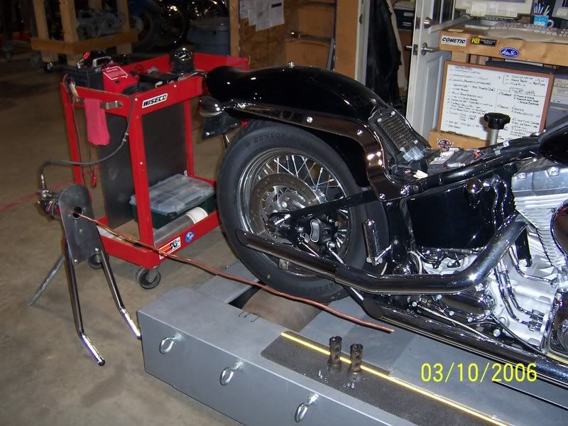
Here's the A-R trap
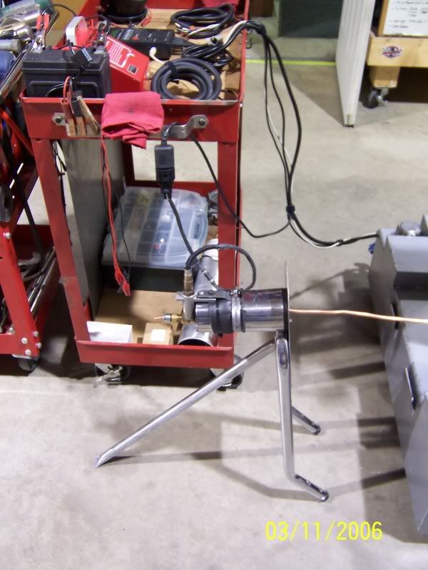
Here's the air-vac
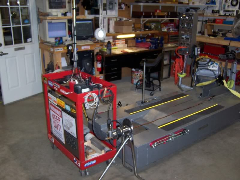
I connect them together like this and run the air-vac form my compressor
That motor looks really nice, now if I could only hear it.
YOU MEAN IT HAS TO RUN TOO!!!!!

Ok, It's just a warm up run, but here ya go (turn up your sound)
 http://www.youtube.com/watch?v=NMCd0SXC9Po
Have a good nite Sum,
Todd


