The plan for 2010 is a complete frame redesign, for several reasons. The oiling problem previously mentioned is one.
Another is the fact that the old frame, being thrown together in haste 2 years ago, prevented me from mounting the carb directly to the head due to the large downtube/oil reservoir. I had to run an extended intake to the carb and this created tuning headaches, including a reversion effect that I could not get past. The long runner actually made positive pressure in a very narrow RPM range (6000-7000 RPM) but the engine would not pull well below or above that range, and I was never able to get into that range in 4th gear.
The long chain run is also eliminated in the new design. Not that it caused any problems at all, but buying that much chain gets expensive after a while.
The biggest benefit is that this design, with the engine mounted to a cradle that bolts to the top of the frame structure, does not limit engine choices. Assuming that the handling and aero work out as well as I think it will, I'll be able to step up in displacement simply by building a new engine mount cradle to fit almost any power plant I care to use. This should make it easier to run in the future by minimizing the amount of rework to run different displacements.
So, here's the basic plan in a computer generated picture, as posted on the garage wall for inspiration.
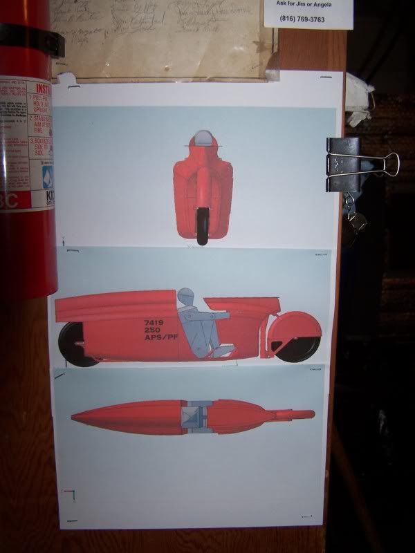
The final fairing shapes are not finalized yet, so this is just a general idea. I'm going with the principle of making as small a hole in the air as possible and leaving it as air smoothly as possible under the rules. (I was really hoping that AMA/BUB would follow SCTA's lead on rear fairing rules, maybe some day.)
The frame was designed with a CAD program that I've started learning to use, and then redesigned several times to match the reality of what I could actually bend and weld in my garage.

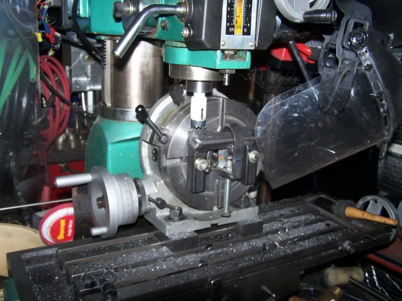
I've always struggled with coping tubing for nice fits, especially when both ends of a tube need to be coped at different angles to the tube and to each other. I came up with a fixture that bolts to my rotary table to hold the tube. With the tube in the fixture on the rotary table, and a digital miter box on the tube for rotational angle, I am now able to cope tubes precisely. Combine this with the CAD program to give good numbers to work with, and I've saved a lot of time getting good fits, and money on wasted attempts.
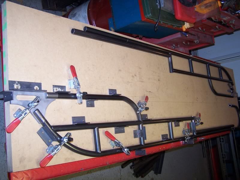
I bought some 3/4 MDF board from Lowe's, and had them cut it in half on their big guided saw. Brought it home and glued the halves together on top of my bike lift. This made a nice flat build table that I could mount angle iron locating fixtures to, along with toggle hold down clamps that I got from Harbor Freight. (not trying to put in plugs for any vendors, just source references in case anyone is interested.)

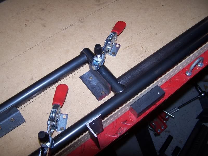
The build table allowed my to make 2 almost identical rear frame sections. I then changed out the fixtures on the table to align the sides and weld in the cross members.
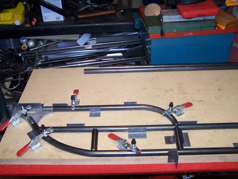
Once the rear frame halves were joined I moved the assembly to my "frame jig" to make sure that the neck would be properly aligned with the rear axle slots. I didn't take any pics while that was happening, I tend to get very one track minded when I'm working on something like that.

Once the neck was located and welded it went back to the table.
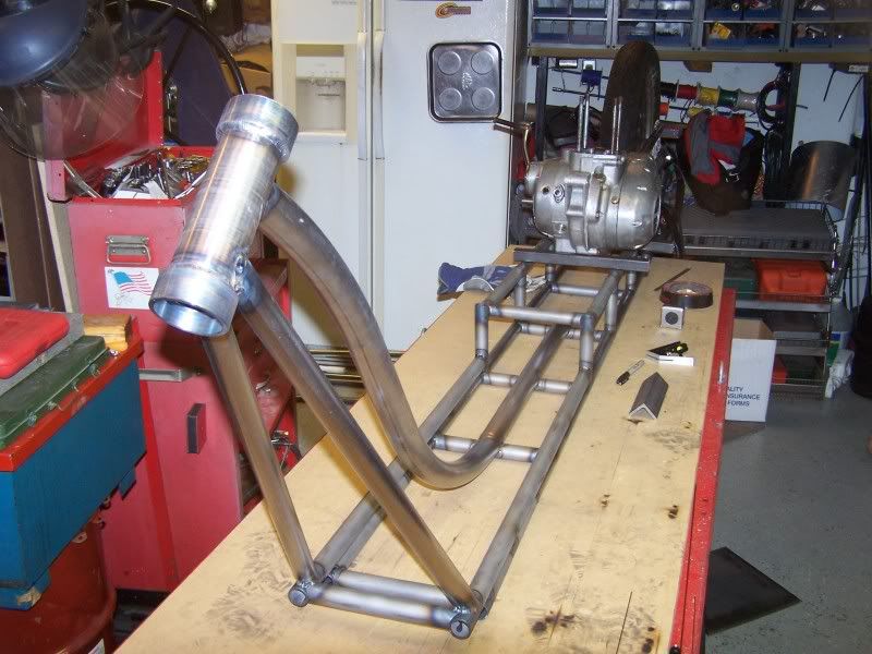
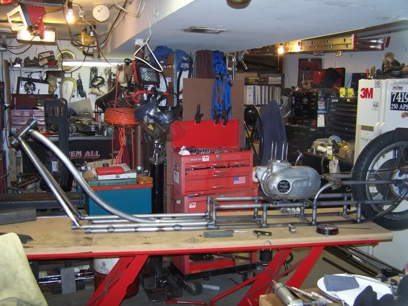
I then set the engine roughly in place to start setting up motor mounts. This was in late December, and is the last thing I did to it. It has been stalled since.

I hate trying to restart a project once momentum has been lost, so I'm hoping putting this up will motivate me to get back in gear, looking at the calendar I'm running out of time already.

I still need to do some gusset work to the frame, and get the engine mounts and other tabs/brackets located, and the seat structure built. Then I'll be able to suit up and assume the riding position while someone traces my aero profile. Then I'll be able to loft the fairing shape and get started on that.
Does anyone have any pointers for making a female mold in one shot without a plug? The CAD program I'm working with will allow me to make full scale profiles from the shape at any spacing I want. I'm thinking I can take the files to a quick print shop and get them printed out full scale, and then use those prints to make an "egg crate" assembly. Fill the spaces in the egg crate with something like expanding foam and then top coat it with plaster. Paint the plaster and then wax the beejeezus out of it with mold release before lay up. Does this plan make sense or is there a better way that I'm not aware of?? I had planned to be at that stage now, but we all know that "life is what happens while we're making other plans".


