Author Topic: Hood scoop questions  (Read 17364 times)

0 Members and 1 Guest are viewing this topic.

Offline John Burk

  • Sr. Member
  • ****
  • Posts: 695
Re: Hood scoop questions
« Reply #30 on: June 15, 2014, 01:26:13 PM »
Should have added , not sure that a nose inlet would work on other than a NACA type streamlined profile . The pressure area would be tiny on a pointed nose and maybe lower pressure and turbulent on a more rounded shape .

Offline Seldom Seen Slim

  • Nancy and me and the pit bike
  • Administrator
  • Hero Member
  • ***
  • Posts: 13162
  • Nancy -- 201.913 mph record on a production ZX15!
    • Nancy and Jon's personal website.
Re: Hood scoop questions
« Reply #31 on: June 15, 2014, 08:33:00 PM »
I still want to know if, IN THEORY, my idea could work.  I don't care if it will be used on a car or bike -- just wonder if there's a way to get around the problem of spilled air making drag - while still giving the engine at least as much as it can use - if not more (presurised).  That was my original question - theoretical.
Jon E. Wennerberg
 a/k/a Seldom Seen Slim
 Skandia, Michigan
 (that's way up north)
2 Club member x2
Owner of landracing.com

Offline Sumner

  • Global Moderator
  • Hero Member
  • ***
  • Posts: 4078
  • Blanding, Ut..a small dot in the middle of nowhere
    • http://purplesagetradingpost.com/sumner/sumnerindex.html
Re: Hood scoop questions
« Reply #32 on: June 15, 2014, 09:19:17 PM »
I still want to know if, IN THEORY, my idea could work.  I don't care if it will be used on a car or bike -- just wonder if there's a way to get around the problem of spilled air making drag - while still giving the engine at least as much as it can use - if not more (presurised).  That was my original question - theoretical.

Work as in reducing drag?  Maybe, maybe not.  If the air you are releasing out the back is turbulent or creates a turbulence there then you probably aren't gaining much.

If you have a scoop that is aero correct for little drag on the back side of it...


.... like on Tom's car above then I think you would be in a loosing situation by loosing that shape and putting on a scoop that is up in the air with an opening back on it.  Just my opinion  :-)

Only way you could really tell would be in a wind tunnel or Woody doing analysis on the exact scoop shape your are purposing attached to the car or bike in question.  I like the option of a second scoop, a flap or other type opening that could be used at slower speeds and closed at higher speeds like John suggested.

Sum

Offline jl222

  • Hero Member
  • *****
  • Posts: 2957
Re: Hood scoop questions
« Reply #33 on: June 15, 2014, 10:51:39 PM »

  OK..what size scoop for 4500 cfm. 29in tires 1.85 gearing 500 cu. in.? :-D

   IF I stick my fist in the inlet tubing while idling the 222 Camaro it sucks my arm in. If I dared to whack the throttle I think it would spit me out the exhaust :-o

         JL222 :cheers:


What boost level so I don't have to make a new spreadsheet using the cfm figure  :-).

With 30 lbs. boost and the other info (not the cfm) and with a 10% oversize about 18 square inches, about 5 inch dia. if round.  If an oval scoop 3 inches high in the middle with rounded ends (1.5 inch radius) the middle section between the rounded ends would be 3.6 inches long so the width of the scoop would be 6.6 inches.

20% over size would be about 20 sq. inches.  I'd probably go with 20-22 sq. inches if it was my car, which it isn't  :-D,

Sum

  The f3-139 is capable of 45+ lbs boost and the inlet is 6in as is all our ducting =28.27 sq in we oblonged the 6 in tube and flared it out to fit a Harwood scoop which is 3 X 15 with rounded ends about 43 sq in,

  Not going smaller for an unknown drag reduction after posting a time of 286 mph at the 21/4 and 294mph and indicated 318mph just short of the end of the ist timed mile and 2 miles to go.

  A spread sheet based on cfm, boost and temp might help. There's low temp boost and hi temp boost with a lot more density in the low. Also supercharging compacts and shrinks the air and it seems that a good supply is needed before the blower,

  The Rolls Royce 2 stage Merlins used a much bigger 1st stage impeller to pump into the smaller 2nd stage impeller as the second stage air is compressed.

            JL222 :cheers:

  PS. I like your inlet placing on Hooleys Stude.


Offline Sumner

  • Global Moderator
  • Hero Member
  • ***
  • Posts: 4078
  • Blanding, Ut..a small dot in the middle of nowhere
    • http://purplesagetradingpost.com/sumner/sumnerindex.html
Re: Hood scoop questions
« Reply #34 on: June 16, 2014, 12:09:52 AM »
.. The f3-139 is capable of 45+ lbs boost and the inlet is 6in as is all our ducting =28.27 sq in we oblonged the 6 in tube and flared it out to fit a Harwood scoop which is 3 X 15 with rounded ends about 43 sq in,....

45 lbs. would be 26 sq. in. with a 20% over cushion, so not far off of you 28 sq. in. but if your 6 inch inlet has been oblonged it isn't 28+ sq. in. any longer, but less.

You guys running at the July meet or Speed Week?  Hope to see you there,

Sum

Offline 836dstr

  • Sr. Member
  • ****
  • Posts: 694
Re: Hood scoop questions
« Reply #35 on: June 16, 2014, 12:38:01 PM »
Hi Guys,

One thing lacking in this discussion (specifically regarding naturally aspirated engines) is clean airflow, turbulence at carb or injector inlet. Ducting and plenum design can be critical. Several years ago I started a thread on plenum design and never really got much information.

Running a D/Street Roadster I started out  using a cutdown Pro Stock hood scoop and ran about 170 MPH. My goal was to eliminate the drag of the hood scoop. I had a one core radiator build and "designed" a bell intake and duct with an expanding volume plenum.

The first run at Bonneville that year we lost 25 MPH. SO MUCH FOR MY GREAT DESIGN! Went to the CARQUEST in Wendover and bought two 11"x 2" air cleaners and ran them into the wind. Next run was right back to 170 MPH.

Just food for thought.

Tom

Offline Sumner

  • Global Moderator
  • Hero Member
  • ***
  • Posts: 4078
  • Blanding, Ut..a small dot in the middle of nowhere
    • http://purplesagetradingpost.com/sumner/sumnerindex.html
Re: Hood scoop questions
« Reply #36 on: June 16, 2014, 01:32:25 PM »
Hi Guys,

One thing lacking in this discussion (specifically regarding naturally aspirated engines) is clean airflow, turbulence at carb or injector inlet. Ducting and plenum design can be critical. Several years ago I started a thread on plenum design and never really got much information.

Running a D/Street Roadster I started out  using a cutdown Pro Stock hood scoop and ran about 170 MPH. My goal was to eliminate the drag of the hood scoop. I had a one core radiator build and "designed" a bell intake and duct with an expanding volume plenum.

The first run at Bonneville that year we lost 25 MPH. SO MUCH FOR MY GREAT DESIGN! Went to the CARQUEST in Wendover and bought two 11"x 2" air cleaners and ran them into the wind. Next run was right back to 170 MPH.

Just food for thought.

Tom

Good info  :cheers:

We have tried to keep our scoop inlets in clean air.  If you don't have wind tunnel data I'd personally keep the bottom of the inlet 6 inches or more above the surface under it.  I'd be affraid to try and design a scoop very close to the body like Speed Demon but I'd bet a lot that they have wind tunnel or CFD data to show that it works there and of course the speeds to back that up.

Likewise with scoop off the sides of the body and naca ducts.  Don't just buy a generic one and stick it on and hope.  You really need to know what the air is doing by these openings and in them as well.  One person who currently has a world record and uses a naca duct for inlet for a blown motor said he would never use one in the same place for a na motor unless he had a lot of data.  A turbo or other compressor can make up for some poor scoop and inlet design since it is drawing air in.  That doesn't mean good design before it isn't important but that it will make up for some mistakes that would hinder one with a na motor.

As you mentioned what happens between the inlet opening and the carb or throttle body is also very important, especially with a carb that needs the booster signals.  We are running a carb on Hooley's car and ....


...Gordon at Superior Air Flow recommended that we add the spacer I made above to the bottom of his carb hat to help with the air going into the carb.  We took his advice and did that....

http://purplesagetradingpost.com/sumner/Hooley%202013/13%20-%20hooley-construction-2013-7.html

At some point the car might be switched to throttle body and EFI.  I think that is more forgiving than a carb since you aren't relying on the throttle body to get the right signals to mix the fuel correctly the injectors will do that.  The carb was a cheaper and much easier thing to do first.  With EFI I think we would of been crazy to of run the car without dyno time like we did with the carb,

Sum

Offline Rex Schimmer

  • Hero Member
  • *****
  • Posts: 2633
  • Only time and money prevent completion!
Re: Hood scoop questions
« Reply #37 on: June 16, 2014, 07:49:05 PM »
I feel the need to put my two cents worth in on air scoop design. We need to consider many things to design an air inlet system that potentially may provide additional air inlet pressure to the engine. The thing that the inlet system should be designed to do is to convert the kinetic energy of the high velocity incoming air into pressure. Again we need to remember the basic rules laid down by Daniel Bernoulli, and that is that air moving fast will be at a lower pressure than air traveling slowly, so what we need to do is get the incoming air slowed down and that is accomplished by increasing the cross sectional area of the ducting that the air is traveling through and providing it with a large volume in which the air will be at a low velocity and higher pressure. Normally aspirated engines will typically be more responsive to this type of inlet because if you could raise the plenum pressure by only 1 psi you would potentially increasing the engine air inlet by almost 7% which should provide an almost equal horse power increase. (This is assuming that you are at STP (Standared Temperature and Pressure) conditions with pressure being 14.7 psi)Turbo/super charged engines see less of an increase because a 1 psi inlet to the turbo/super charger on a engine that is running at say 20 psi boost above atmospheric is only going to see a 2.9% potential increase and the more blower boost the less the percentage of increase will be from a well designed inlet. The increase in cross section area should start immediately after the inlet, the angle that the sections increases needs to be low enough to prevent the incoming air from separating from the duct surface and any attempts to change the direction of the air flow need to be gradual. Runs of constant diameter or cross section will begin to act as a choke as the boundary layer thickens and reduces the area that the high velocity air flow passes through. This is especially true with rectangular shaped cross sections as the thickening of the boundary layer along the long sides of the rectangle can greatly reduce the effective area rapidly. You also need to pay attention to the edge radius of the inlet itself,most of us typically use some sort of formed radius or a piece of formed round tubing to make the inlet radius better is to make the radius similar in cross section to the leading edge of a wing section, which can greatly affect the efficiency of the inlet. (Pain in the a$$ to make!)

A note on John's(JL222) super charged hemi, for 4500 cfm at 300 mph you need a cross section area of 24.5 sq. inches which is a tube with an inter diameter of 5.6 inches so a 6 inch I.D tube would be about 15% over sized at that speed so it is probably a good fit. If you are not concerned about "air spillage" due to the inlet tract being to large I could not see a reason to increase the inlet size to 7 or even 8 inches in diameter, one thing that is happening with a turbo/supercharger like yours with the blower inlet facing forward it that the air that is traveling through the duct stops as soon as it hits the back of the duct ,i.e. pressure recovery, and that is where your inlet is so it should benefit from additional inlet pressure.

Regarding SSS's thought about bleeding air out of the plenum, what is happening is that the bleeding increases the air velocity in the duct and plenum and therefore reduces the pressure recovery. This typically can increase overall aero drag due to the increased velocity in the air inlet system and also if the vented air is not discharged into a low pressure it could, as Sum pointed out, actually increase drag.

Probably the best example of a variable inlet configuration is the SR-71, the large "spear point" that you see protruding from the front of the engine inlet is moved froward as the planes speed increases this does two things, it reduces the area of the inlet and also increased the volume of the plenum in front of the engines inlets which keeps the inlet velocity below sonic.
Rex


Rex

Not much matters and the rest doesn't matter at all.

Offline RidgeRunner

  • Sr. Member
  • ****
  • Posts: 843
Re: Hood scoop questions
« Reply #38 on: June 17, 2014, 07:12:08 AM »


Probably the best example of a variable inlet configuration is the SR-71, the large "spear point" that you see protruding from the front of the engine inlet is moved froward as the planes speed increases this does two things, it reduces the area of the inlet and also increased the volume of the plenum in front of the engines inlets which keeps the inlet velocity below sonic.
Rex


[/quote]


     Might a more blunt/rounded "spear point" work better at the speeds most current LSR vehicles run if such a system were applied to them?

                Ed


Offline WOODY@DDLLC

  • Hero Member
  • *****
  • Posts: 1806
  • ECTA made it to AR-Kansas!
    • Design Dreams, LLC
Re: Hood scoop questions
« Reply #39 on: June 19, 2014, 05:07:26 PM »
Been on the road so here is some more food for thought!
I think you can see the relationship between mph and scoop size better if it is graphed. The % between the mph is the change in area. The inlet area would have to change a lot from 50 mph to 250 mph. You can see why the drag guys want a bigger hole for the first 60 feet! And they are accounting for the drag hit at the far end, too! Could be done but you have to ask is it worth it and can you package it, operate it and still meet the rule book?  :?
The RAM air chart is the theoretical psi for a CLOSED scoop. Turn the engine on and the density inside the scoop WILL drop with a column of air opening! The CFM numbers will match just fine at the inlet but the air WILL be thinner! IMHO, the hardest part is getting the pressure balance at the boosters or a compressor face!  :x
All models are wrong, but some are useful! G.E. Box (1967) www.designdreams.biz

Offline Dynoroom

  • Global Moderator
  • Hero Member
  • ***
  • Posts: 2192
Re: Hood scoop questions
« Reply #40 on: June 19, 2014, 05:43:16 PM »
Woody, I get the air balance @ the boosters issue but go into your thoughts about balance on the compressor face.
In my simple world I just want to recover as much altitude as I can. So if I'm at 29.95 at home & 25.50 at Bonneville I would like to get the ~4" hg back. This is to keep my turbo pressure ratio as close to the dyno test as possible. If the we run at a higher altitude with no pressure recovery the turbine will spin faster to make up for the higher pressure ratio and will cause more back pressure. Some of us fight excessive system back pressure for added performance.   
Your thoughts.
Michael LeFevers
Kugel and LeFevers Pontiac Firebird

Without Data You're Just Another Guy With An Opinion!

Racing is just a series of "Problem Solving" events that allow you to spend money & make noise...

Offline Sumner

  • Global Moderator
  • Hero Member
  • ***
  • Posts: 4078
  • Blanding, Ut..a small dot in the middle of nowhere
    • http://purplesagetradingpost.com/sumner/sumnerindex.html
Re: Hood scoop questions
« Reply #41 on: June 19, 2014, 08:43:10 PM »
....In my simple world I just want to recover as much altitude as I can. So if I'm at 29.95 at home & 25.50 at Bonneville I would like to get the ~4" hg back. This is to keep my turbo pressure ratio as close to the dyno test as possible. If the we run at a higher altitude with no pressure recovery the turbine will spin faster to make up for the higher pressure ratio and will cause more back pressure. ...

I'll also be interested in what Woody has to say.

I ran some numbers through BW's Matchbot using the turbos we have on the Stude but for a 500 ci motor, vs. the 572 in the car, at 6500 rpm.

Altitude..  temp.. lbs. boost..Compressor Pressure Ratio..HP..Compressor Outlet Temp..Exh. Manifold Pres
Sea level.....90.......16#......................2.16..............1385...............296 F.......................18#
4600...........90.......16#......................2.33..............1297...............319 F.......................18#
4600...........90.......18#......................2.49..............1384...............339 F.......................20#

From sea level to 4600 feet you loose about 100 HP at the same boost and the air temps out of the compressor go up about 23 degrees.  To get that back you need to run 2 more lbs. of boost 18 vs. 16 and that raises the compressor outlet temps 43 deg. over sea level.  Also as you mentioned the Pressure Ratio has gone from 2.16 to 2.33 and then 2.49.

So making up any of the altitude loss is going to be big in the terms of the compressor not having to work so hard to make up for it and the intercooler also doesn't have to cool hotter air.

Our present setup on the Studebaker sucks and we know it, in that we have no plenum area before the compressor inlets.  This might be fixed this year but I kind of doubt it at this time.  The only saving grace for us is that we are not trying to run anywhere near what the combo should be capable of if everything was maximized.

How about it Woody, would feeding the air from the scoop inlet into a crude box ....


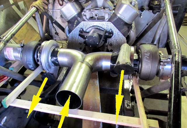
...before the two turbos help in the area above where the "Y" is now.  They would each draw out of opposite sides of the box.  Would this help our pressure recovery?  We would also make the track from the inlet to the box a constantly expanding volume.  We did that on the scoop for the old motor with the inlet track expanding from the inlet to the bug catcher on the roots blower, no plenum though.

One thing we all find is that sometimes what is best either can't be done in time if you ever want to run or it just won't fit in the car.... :-D :cry:

Sum
« Last Edit: June 20, 2014, 12:30:43 AM by Sumner »