Author Topic: Roll Cage Base Plate FEA?  (Read 43890 times)

0 Members and 1 Guest are viewing this topic.

Offline Saltfever

  • Full Member
  • ***
  • Posts: 276
Roll Cage Base Plate FEA?
« on: January 09, 2012, 07:42:00 PM »
I have had a concern about the roll cage base-plate thickness ever since the rule book changed from 1/8 thick material to 1/4” thickness a couple of years ago. I think an accident analysis was the reason for the change but since analysis is never shared in public the technical reason is unknown. Although, one might guess that a roll bar tube punched through the 1/8” base plate. I totally support SCTA’s decision to want a safer cage attachment. However, without access to FEA or the SCTA analysis I am concerned about the “improvement” on thin structures.

Is there anyone here that could FEA model a 1.625” or 1.750” roll cage upright tube loading the rule-book-base-plate welded to unibody body sheet metal with maybe two thicknesses (0.035” and 0.065”)? For load would 15-20Gs on a 3,800lb car be reasonable?

Offline hotrod

  • Hero Member
  • *****
  • Posts: 1231
    • Black Horse photo
Re: Roll Cage Base Plate FEA?
« Reply #1 on: January 10, 2012, 12:17:13 AM »
Comment regarding welding thick base plates to thin unibody structures.

The debate about how you weld a 1/4 inch thick plate to perhaps 18 - 20 gauge sheet metal got me to thinking and my first thought was to put a sheet steel doubler on the sheet metal structure that is larger than the base plate of the roll bar. Say for example you have a 6" square 1/4 thick plate, put it on top of a 7" square piece of 16 gauge that is stitch welded and plug welded to the sheet metal structure. That way the 1/4" plate has a much more difficult time trying to cookie cutter through the body structure as it has to shear 2 pieces of thin sheet metal rather than a single layer of sheet steel. There might be some concern about the strength of attachment of the doubler plate, so options include photographs taken during fabrication showing the matrix of plug welds hidden under the 1/4 inch plate, or use backup bolts to provide redundant attachment.

After that thought had passed I realized that the rule does not specify the edge shape on the 1/4" plate. I see no reason why the 1/4" base plate could not be full 1/4" thickness for the required surface area with a wide bevel at perhaps 30 degrees beyond that so the actual weld occurs between similar thickness materials.

This latter method would avoid the issue of concern about the strength of attachment of the thin doubler plates, and give more inches of perimeter to the base plate and a more ductile edge which might give under extreme impact rather than trying to cut a disk of sheet metal out of the body work.

Just some food for thought!

Larry

Offline johnneilson

  • Sr. Member
  • ****
  • Posts: 502
Re: Roll Cage Base Plate FEA?
« Reply #2 on: January 10, 2012, 12:20:36 AM »
Not having witnessed the failures around LSR, I can only comment on SCCA cars.
The trend has been to go from 1/4" plates down to .080 min thickness (last GCR I had '09).
The issues I have seen are not the roll structure penetrating the foot, it is the foot tearing out the flooring under it. It is my understanding that the lesser material will deform and stay attached to the sheet steel without tearing.

IMHO, the materials used are secondary to the design and attachment of cage. The last car I caged, Miata open top had 20 points of attachment to the car. Of course, it was to help stiffen the chassis so it picked up the front suspension points and the rear sub frame mounts. Also, because it is a small car the cage mounted not on the floor, but on top of the rocker panel structures. All the attachment points (footings) were .120 plate and about 36 sq/in.

somewhere I have a video of a Mustang going on its lid and you can see the cage feet punch through the floor.

I will try to model up a few plates and upload them later.

John
As Carroll Smith wrote; All Failures are Human in Origin.

Offline Saltfever

  • Full Member
  • ***
  • Posts: 276
Re: Roll Cage Base Plate FEA?
« Reply #3 on: January 10, 2012, 03:37:39 AM »
Edit . . .  the rule does not specify the edge shape on the 1/4" plate. I see no reason why the 1/4" base plate could not be full 1/4" thickness for the required surface area with a wide bevel at perhaps 30 degrees beyond that so the actual weld occurs between similar thickness materials.

This latter method would avoid the issue of concern about the strength of attachment of the thin doubler plates, and give more inches of perimeter to the base plate and a more ductile edge which might give under extreme impact rather than trying to cut a disk of sheet metal out of the body work.
Larry

Excellent idea, Larry. The beveled edge (maybe as much as 60 degrees) would tend to yield and therefore spread the force over a larger area. Anything to promote yield or ductility rather than shearing seems prudent. The welding of similar thickness should encourage.

I’m having trouble getting small pictures be accepted. I’ll try the pics in another post.
« Last Edit: January 10, 2012, 03:41:38 AM by Saltfever »

Offline Saltfever

  • Full Member
  • ***
  • Posts: 276
Re: Roll Cage Base Plate FEA?
« Reply #4 on: January 10, 2012, 04:30:10 AM »
Edit . . . The issues I have seen are not the roll structure penetrating the foot, it is the foot tearing out the flooring under it. It is my understanding that the lesser material will deform and stay attached to the sheet steel without tearing.  I will try to model up a few plates and upload them later. -John

(Edit) I am having trouble getting the pictures posted. It could be late night server problems.
The cars in the pictures have the ¼” plates welded to 0.035” sheet metal floor pans. Both cars are tech approved for >200mph. Welding ¼” thick plate to thin sheet metal begs a few questions. Neither car is mine but I have the same model and have measured the pan thickness in those areas.

SCTA does not share publicly any technical analysis. In our litigious society I can certainly understand, respect, and support that position. However, sometimes the lack of technical information raises questions. I am not saying the rule is unfounded or without merit. I am just concerned, but I lack the technical or engineering data to discuss this with the SCTA principals. If good data showed my concerns were wrong I would be at peace.

John you can see what is going on here. In addition to the straight plate could you model Larry’s idea with a 30 or 60 degree beveled edge? FEA or anything else that brings a better understanding is greatly appreciated.
« Last Edit: January 10, 2012, 04:34:34 AM by Saltfever »

Offline Saltfever

  • Full Member
  • ***
  • Posts: 276
Re: Roll Cage Base Plate FEA?
« Reply #5 on: January 10, 2012, 04:33:28 AM »
Here they are: Please no comments on the weld quality or anything else. The car owners graciously let me take these pictures to help me. Pictures are only to demonstrate the rule book requirement of 1/4" base plates. The floor they are welded to is .035" sheet metal. Is this the best solution?
« Last Edit: January 10, 2012, 04:41:19 AM by Saltfever »

Offline SteveM

  • Hero Member
  • *****
  • Posts: 1483
Re: Roll Cage Base Plate FEA?
« Reply #6 on: January 10, 2012, 09:56:36 AM »
My 2 cents (as a newcomer to this sport), but as a metallurgical engineer with 20 years of professional experience.  My thinking is that the photos shown above are not the ideal situation from either a welding standpoint (welding thick to thin), or a structural standpoint (tearing of the weld seams).

My thinking is as follows, and it may not be 100% right, but I'll put it out there anyway....  Since the roll cage tubing thickness is specified as 0.120" nominal wall thickness, I would personally prefer to see the base plate thickness match more closely with the tubing thickness specification. 

If the base plate requirement for unibody cars was for 1/8" thick material, but with a larger base plate size (more perimeter area), I think the attachments would be more structurally sound.

My opinion here is not intended to stir any political issues (if there are any), only to provide my own technical viewpoint on this issue.

Steve M.
1/2 of the Rampage Brothers

Offline Dean Los Angeles

  • Hero Member
  • *****
  • Posts: 2370
Re: Roll Cage Base Plate FEA?
« Reply #7 on: January 10, 2012, 11:03:52 AM »
Did they lose you at FEA?
If you have a single post and put a 50 pound weight on top you know what the load on the bottom of the post is going to be.
If you have something like a roll cage and try to figure out the possible paths of stress it isn't something you can do on a spreadsheet, much less in your head.

Finite Element Analysis (FEA)) is a numerical technique for finding approximate solutions of partial differential equations (PDE) as well as integral equations.
What? That didn't help either? Don't ya hate the guys that use big words????

OK, a picture is worth a thousand words.


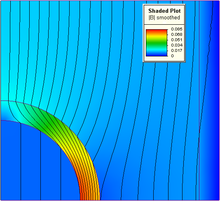
FEA is a computer modeling program that allows you to simulate stress loads and calculate the stress through the part.

My input on the 1/4" plate is that the 1/8 plate was viewed as insufficient to carry the load. What it doesn't address is how the load is transferred to thin sheet metal. This doesn't require FEA to figure out. Weld the 1/4" plate to the thin sheet metal. Weld a 10 foot tube on the 1/4" plate and then wiggle the end of the tube. What part of the system is flexing? The sheet metal. You have to spread the load and stiffen the underlying structure to avoid tear out or punch through.


Ultimately you end up at .035, you have to spread the load to reduce the stress to manageable levels. I would use a plate as large as shown (WRC rally car) with a similar plate on the other side.
Well, it used to be Los Angeles . . . 50 miles north of Fresno now.
Just remember . . . It isn't life or death.
It's bigger than life or death! It's RACING.

Offline Dynoroom

  • Global Moderator
  • Hero Member
  • ***
  • Posts: 2192
Re: Roll Cage Base Plate FEA?
« Reply #8 on: January 10, 2012, 11:20:02 AM »
Dean has got the bull by the horns here, and he even stopped and had a "sandwhich". The rule book allows you to bolt together 2 plates top and bottom (or weld) to the floor. This is deemed the best solution using a unit-body at this time.
If during this conversation a better process is proven to emerge two things can happen. 1) you can always add or have more safety features, no rule against that. 2) submit said information to the SCTA befor the due date for next years rules change.
Michael LeFevers
Kugel and LeFevers Pontiac Firebird

Without Data You're Just Another Guy With An Opinion!

Racing is just a series of "Problem Solving" events that allow you to spend money & make noise...

Offline hotrod

  • Hero Member
  • *****
  • Posts: 1231
    • Black Horse photo
Re: Roll Cage Base Plate FEA?
« Reply #9 on: January 10, 2012, 11:56:35 AM »
I think we are thinking about the same thing Saltfever, regarding the bevel.
I just did not specify which reference the bevel angle was from.
I was thinking 30 degrees from the horizontal.

Note that in World Rally Cup they skip weld many of the sheet metal panels to stiffen the car, it is lighter, uses less weld wire and time, and is just as strong as a continuous weld and more resistant to unzipping a weld as it has to start a new fracture each time it breaks a weld.
The thinner edge at the weld point will also facilitate much better fitup on the weld seam as a bit of persuasion with a Mark I big hammer will get a close fit between the sheet metal base and the support plate perimeter.

Larry
« Last Edit: January 10, 2012, 12:03:18 PM by hotrod »

Offline Saltfever

  • Full Member
  • ***
  • Posts: 276
Re: Roll Cage Base Plate FEA?
« Reply #10 on: January 10, 2012, 04:24:03 PM »
Thanks for the clarification, Larry. I would probably not leave a sharp edge on the perimeter. It might be best to leave an edge thickness equal to 1x or 2x the floor pan thickness. You know, stuff like the HAZ or burn back on the edge would be less problematic and the filet would be more closely matched to the substrate.

Welding engineers your opinions are welcome.

 
« Last Edit: January 10, 2012, 04:29:26 PM by Saltfever »

Offline Saltfever

  • Full Member
  • ***
  • Posts: 276
Re: Roll Cage Base Plate FEA?
« Reply #11 on: January 10, 2012, 05:27:56 PM »
Did they lose you at FEA?
Finite Element Analysis (FEA)) is a numerical technique for finding approximate solutions of partial differential equations (PDE) as well as integral equations.
What? That didn't help either? Don't ya hate the guys that use big words????
Dean, if you are going to cut and paste a definition from Wikipedia it would be nice to see them get the credit! But at the very least, if you are going to directly copy text from another source, adding quotes shows respect and not plagiarism.

No, they did not lose me at FEA. I am the one that started this thread looking for FEA help.  Even though I am not a structural engineer I started using FEA with NASTRANS. In the late 80’s I moved to Algor and then moved to Inventor just when they incorporated FEA into that package. Unfortunately, I have been away from those wonderful tools for almost 10 years. You know the old saying “use it or lose it”!  Well, that is why I am seeking help from anyone that can make a contribution to a better understanding of the base-plate design. I’m missing the tools and my grey matter is rusty.

I am quite used to the tone of most of your postings so I’ll try and describe the purpose of this thread in my reply to Mike below. Your interest and help is appreciated.

Offline Saltfever

  • Full Member
  • ***
  • Posts: 276
Re: Roll Cage Base Plate FEA?
« Reply #12 on: January 10, 2012, 05:41:49 PM »
Hi Mike and thank you for taking an interest in this thread. I’ll fill you in on why I am posting here. After the plate thickness was changed a couple of years ago I had a very brief talk with Lee Kennedy. Of course, Lee had all the information leading up to the decision and I had zero. Last summer I again talked to both Steve and Lee individually trying to get a better idea of the technical thinking for the increase in thickness. Both of them are supportive but as you know neither of them could share any SCTA analysis or the causative factor leading to the change. I am not being negative; I respect the process and their careful regard for disseminating information. I have no vendetta and no mission. Poor Lee and Steve are constantly bombarded with opinions. “Without data I’m just another guy with an opinion”!  :-D  I simply want a better understanding about the design so I can discuss it more intelligently with Lee. I have fallen behind the technology but there are others here that are smarter and current. I am only in research-mode, hoping that others will help me develop an accurate picture of the thick plate welded to very thin sheet metal. The thick plate welded to thicker material is not a concern.

I agree that load paths and cage geometry are very complicated. I am simply focusing on one aspect of the design. Whether it is welded or sandwiched, under load the perimeter is introducing shearing force into the substrate. I would like to see data, and not opinion, to eliminate my ignorance. 

Offline Dean Los Angeles

  • Hero Member
  • *****
  • Posts: 2370
Re: Roll Cage Base Plate FEA?
« Reply #13 on: January 10, 2012, 06:00:05 PM »
Sorry, wasn't directed at you. There are lots of readers that don't know what FEA is. Trying to give some extra help. Wasn't pointed at any one person.

Didn't quote wikipedia because it wasn't pertinent. Just quoting the jargon.

Quote
I am quite used to the tone of most of your postings
Ooooh, didn't know I had a tone! I hope the tone is melodic, not jarring.

Peace, love, out.  :mrgreen:
Well, it used to be Los Angeles . . . 50 miles north of Fresno now.
Just remember . . . It isn't life or death.
It's bigger than life or death! It's RACING.

Offline hotrod

  • Hero Member
  • *****
  • Posts: 1231
    • Black Horse photo
Re: Roll Cage Base Plate FEA?
« Reply #14 on: January 10, 2012, 06:22:41 PM »
Quote
Thanks for the clarification, Larry. I would probably not leave a sharp edge on the perimeter.

Agree I was thinking of leaving a thickness of about 2x the sheet metal thickness you are welding to also.
As you mention a sharp edge tends to pull back as it gets up to welding heat so you would definitely want to leave a bit of material on the bottom edge of the bevel edge so you have stock to weld too.

I think we are very much in agreement on the general layout.

One interesting thing to include in the finite element analysis would be the ideal thickness of that weld edge to allow flex and energy absorption at the plate edge to minimize the possibility of shear failure of the floor pan sheet metal by allowing the base plate to work with the sheet metal under plastic deformation without pulling welds out of the sheet metal.

Sometimes stronger is actually achieved by allowing some planned flex in the design structure, so no single point overloads and fails completely. You also want it to fail gracefully which is what skip welds and plug welds would give you. A severe impact might break one or two skip welds or plug welds but the other welds would have to undergo the full fracture development process from scratch, where a continuous perimeter weld once is starts to fail in shear or tearing at a corner or some other stress concentration point can just unzip as the fracture migrates around the perimeter of the plate.

Larry